Os cruzamentos são
extremamente importante para sistemas de alto-falantes e um
grande razão pela qual somos capazes de obter a qualidade de som que amamos.
Por outro lado, coisas como frequência de crossover (Fc), declives (db por oitava e como tudo funciona podem ser um pouco complicados se você não entender como tudo funciona. Eu adoraria ajudar!)
Neste artigo vou explicar:
- O que é a frequência de cruzamento Fc e por que é importante
- O que é uma inclinação cruzada e a mais comum que você encontrará
- Como calcular a queda de cruzamento de dB para frequências incluindo Fc
- O papel dos indutores e capacitores (e “reatância” para Fc)
Fc de frequência de cruzamento e inclinações de cruzamento explicadas
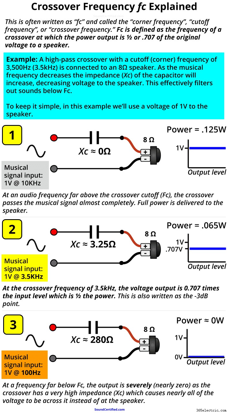
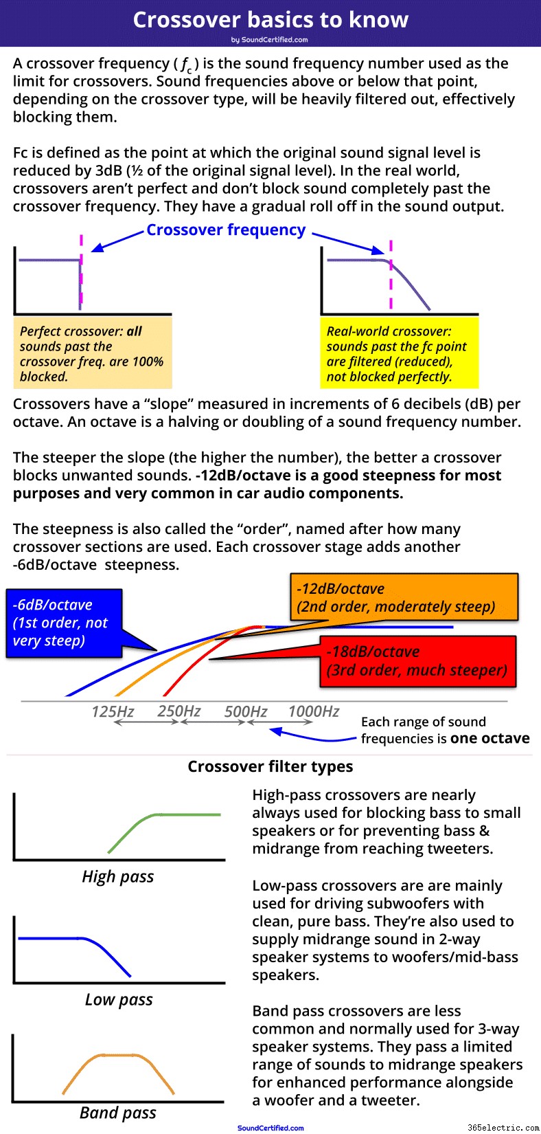 Este diagrama mostra exemplos dos 3 principais tipos de filtros usados em cruzamentos. Também são mostradas as inclinações de cruzamento mais comuns que é a "inclinação" do filtro (com que eficácia eles bloqueiam frequências além da frequência de cruzamento). Uma frequência de cruzamento, comumente escrita como Fc , é o ponto de frequência de áudio em Hertz (Hz) no qual o crossover fornece saída de potência de -3dB (1/2) ao alto-falante. Fc é o ponto de marcação após o qual as frequências de som serão bastante reduzidas para evitar que cheguem a um alto-falante.
 Passado o ponto de frequência de crossover (Fc), a potência de saída do crossover cairá cada vez mais, com cada vez menos potência enviada ao alto-falante. Acontece que
em Fc, a tensão de saída para a carga (alto-falante) é 0,707 x a tensão de entrada, o que significa que você pode calcular a queda de decibéis com base na tensão de saída versus a tensão de entrada. Por que as frequências de cruzamento são importantes
Ao projetar cruzamentos de alto-falantes, a frequência de cruzamento (
fc ) é usado como uma espécie de linha que marca onde queremos começar a bloquear as frequências de som enviadas para um alto-falante. Geralmente é baseado nas especificações fornecidas por um fabricante de alto-falante que lista as frequências de som que um alto-falante pode produzir com boa resposta de som e sem distorção.
Por exemplo, os tweeters não podem tocar notas graves da música e podem até ser danificados por elas. Sabendo disso, gostaríamos de escolher uma frequência de crossover alta o suficiente para bloquear as notas graves enviadas aos tweeters para evitar distorções ou danos. (Tipicamente os tweeters têm frequência de cruzamento nos milhares de Hertz [escritos como KiloHertz ou kHz para abreviar] como 3,5 kHz, 5 kHz e assim por diante -
bem acima da faixa de sons graves e médios na música).
Uma frequência de cruzamento às vezes também é chamada de frequência de canto ou frequência de corte já que pensamos em como os sons são “cortados” após esse ponto. A frequência de cruzamento Fc é muito importante para o design de crossover
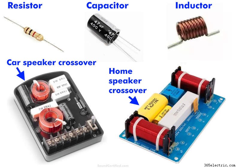 Os crossovers de alto-falante (também chamados de “passivos”, pois não usam energia elétrica para operar) usam capacitores e indutores que são selecionados com base nos valores das peças disponíveis e seu custo. Um crossover é projetado com base em uma frequência Fc inicial e ajustado conforme necessário para os objetivos do projeto.
 O uso da frequência de crossover Fc como ponto de partida permite que os projetistas de sistemas de alto-falantes calculem os valores de parte necessários (capacitores e indutores) dependendo da impedância do alto-falante. Como você não pode comprar peças em qualquer valor, o Fc que obtemos com base no que queremos é um bom ponto de partida com o qual podemos trabalhar e ajustar conforme necessário para trabalhar com peças com base na disponibilidade, preço e outros fatores.
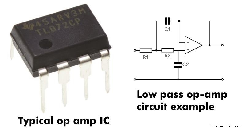 Os amplificadores operacionais, também chamados de amplificadores operacionais, são o bloco de construção mais importante para crossovers eletrônicos. Os crossovers eletrônicos executam exatamente o mesmo trabalho (e têm o mesmo comportamento básico) que os crossovers passivos (falantes). A diferença é que eles funcionam em sinais de baixo nível antes eles são amplificados enquanto os crossovers passivos funcionam com sinais amplificados depois a saída do amplificador. OBSERVAÇÃO:
 Neste artigo, enquanto descrevo como os crossovers passivos (não eletrônicos, não alimentados) e o Fc funcionam, os princípios são exatamente os mesmos para os filtros eletrônicos.
Assim como seus maiores capacitores passivos ou contrapartes baseadas em indutores, os crossovers baseados em amplificador operacional têm as mesmas inclinações e comportamento de frequência de crossover. Eles simplesmente fazem isso com o sinal
antes é amplificado em vez de depois dele.
How to calculate decibels (dB) for the crossover frequency Fc
All sound frequencies after the crossover frequency are cut more and more past it with an increasingly steep reduction – to the point where they’re almost completely blocked.
In other words,
a crossover filters out a range of sounds you’d like to prevent reaching speakers, starting at the crossover frequency. In the electrical engineering world, we traditionally use decibels (dB) when we talk about power measurements since they’re often non-linear. This just means that mathematically, power is often measured, charted, and tracked using exponential math such as logarithms (“10 to the power of x”, for example).
How crossover frequencies (Fc) and dB are related
Because crossovers reduce power at their output, it’s pretty common to measure the output reduction in decibels. One reason for this is that they have a gentle “slope” (downward curve) rather than a straight line if you were to see them graphed across the full range of audio frequencies.
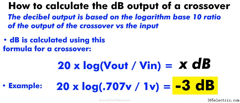
For that and other reasons, we can measure the power output reduction in dB. To do so, you’ll need to know either (1) the power before and after the speaker/from the amp, or (2) the voltage at the speaker and from the amp.
Knowing those, you can easily calculate the dB output of a crossover with a scientific calculator on your computer or smartphone.
You can calculate dB for a crossover using these formulas: - For voltage: 20 x log(Vout / Vin ) =x dB
- For power: 10 x log (Power_out / Power_in) =x dB
Understanding crossover signal level in vs out and “negative gain”
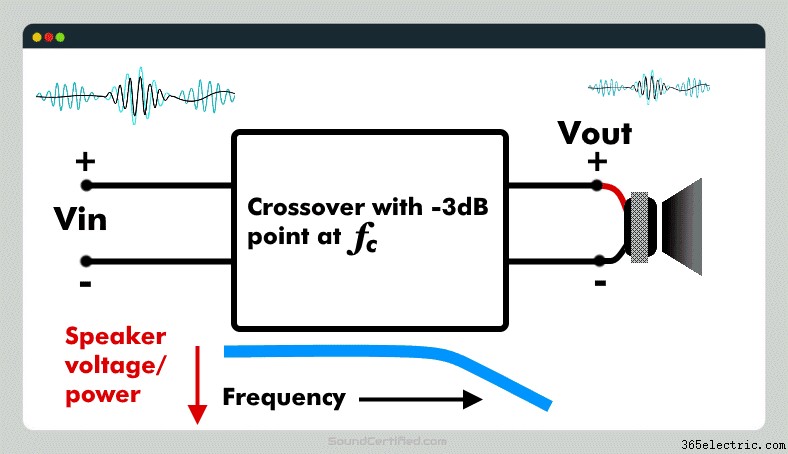 Crossover voltage out (called here “Vout”, the voltage to a speaker delivered from a crossover) can never be higher than the input – that’s not possible.
 Crossovers can only
reduce the input directed to a speaker – they can’t amplify it. Some electronic crossovers do, but those intentionally have a gain on purpose and that’s not common in most cases.
For that reason, you’ll always get a negative dB answer if you do the math for the output of a crossover.
For the record,
a negative dB value is used to show a reduction in engineering math while positive usually means a gain or increase in a signal. Amplifiers have a positive dB output (gain) while crossovers and some other components like resistors have a
negative gain (a negative dB effect on a signal).
Attenuation is another way of describing a negative gain.
Observação: the gain control of an amplifier is there to compensate for a high or low input signal level and is a separate section from the crossover circuitry.
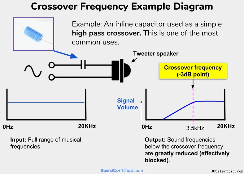
How a crossover frequency Fc works:example diagram
 An example of a very common and simple high-pass crossover. A capacitor in series with a speaker will allow higher frequencies (above Fc) to pass with almost no volume or power drop to the speaker. It acts as a zero Ohm resistor (a short circuit wire) in series with it . However, for audio frequencies below Fc, the “resistance” (impedance, called capacitive reactance) of the capacitor will increase, allowing less and less voltage &power to reach the speaker. It will act like a very high-value resistor in series and therefore will block most of the signal from an amp sent to the speaker. In other words, a high-pass filter!
 One of the problems I’ve found when we’re talking about this topic is picturing it in your mind. For example, it can be hard to understand
what actually happens in real life when actually playing music in the real world vs just some explanation you’ve found on the internet.
All crossovers work the same – understand one, you understand them all (well, mostly!)
One important note I need to make is that
the principles are the same regardless of the number of “orders”, or stages, a crossover has. For example, a simple 1st order crossover with a capacitor connected inline with a tweeter works on exactly the same principle as a fancier 2nd order 2-way crossover.
It’s just that the details are a little bit more complicated – not
how it works. That part never changes.
There are some crossovers with more sophisticated features &designs I won’t get into here, but for the most part, the majority are all the same and do the same thing to varying degrees. The great thing is that once you understand the basics very well, you’ve got it figured out for the most part!
The fundamentals of how crossovers work with Fc
The most important thing to know is that
crossovers work by “absorbing”, or preventing, voltage and power from going to the speakers they’re connected to for the sound frequencies we don’t want them to play. In the example from my diagram further above, you can see that:
- Above the cutoff frequency Fc, a capacitor acts like an almost zero resistance connection – nothing is blocked and it acts almost like a straight section of wire.
- When audio frequencies begin to reach Fc, the impedance of the crossover goes up, acting like a high-value resistor in series with the speaker. At Fc, the speaker receives only 1/2 the power it would otherwise (which also happens to be .707 times the input voltage from the amp or stereo).
- The farther we go past the Fc limit, the crossover’s impedance is much bigger in Ohms; in fact, past a certain point, it will be several hundred Ohms typically. When that happens the speaker has about 0v and no power to it.
As you can see elsewhere in my article, the “steepness” of the drop in the power &signal level to the speaker depends on the crossover slope. A crossover’s slope is basically just a result of how many “stages”, or crossover sections, are used as needed for the particular speaker system or speakers we’re working with.
Crossovers like you see here and
are always in increments of 6 decibels (dB) Per Octave: - 1st order crossover: a single capacitor or inductor is used, -6dB per octave reduction (not very steep).
- 2nd order crossover: Two components sections are used:one capacitor, one inductor. –12dB/octave reduction (steeper, more effective, very popular).
- 3rd order: two capacitors + 1 inductor or 2 inductors + 1 capacitor are used:–18dB/octave cutoff.
..and so on, with -12db being one of the most common crossover slopes you’ll find for both car audio crossovers and home audio speakers too.
An octave is just a half or double of an audio frequency. For example, 200Hz is an octave of 100Hz, 400Hz is one octave of 200Hz, then 800Hz, and so on. Equalizers and other audio electronics may use other variations with finer numbers like 1/3 octave, for example.
Crossover frequency formula math:inductive and capacitive reactance explained
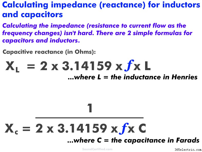 Shown here are the basic formulas for simple 1st order crossovers using capacitors and inductors. Capacitors have an impedance (Ohms) value that depends on the frequency just like inductors do.
 Capacitors and inductors have a “resistance” called
reactance (in Ohms just like resistance) that depends on the frequency. Here are a few basic things to understand:
- Capacitive reactance increases as the frequency DECREASES. It’s normally written as “Xc.” Capacitance is marked in units of Farads, with most capacitors being values in the microFarad (uF) range, nanoFarad (nF), or even picoFarad (pF).
- Inductive reactance INCREASES as the frequency increases. It’s normally written as “Xl.” Inductance is marked in units of Henries and typically found in units of microHenries (uH) or milliHenries (mH).
Note:“ Micro” units are 1 x 10E-6 decimal places (ex. .000 001) while “nano” represents 1 x 10E-9 decimal places (ex. .000 000 001).
Again, it both cases, it’s just a form of impedance much like how a speaker voice coil that has a certain amount of inductance due to the coil of wire inside does. Both are measured in Ohms (Ω).
However, they complement each other and behave pretty much like the opposite of each other. Por exemplo:
- Capacitors act like high-pass filters when connected in series and low pass filters in parallel.
- Inductors act like low-pass filters when connected in series and high-pass-filters in parallel.
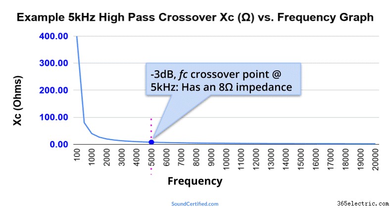 This graph shows an example of a simple high pass capacitor using a 3.98 microFarad capacitor with an 8Ω speaker with a crossover frequency (Fc) of 5kHz. At the Fc value, the impedance is the same as the speaker load (8Ω) which means the speaker power has dropped to 1/2. Further below Fc the impedance grows higher and higher, blocking bass frequencies more and more.
 More great crossover and audio articles you’ll love
Don’t miss out on these
fantastic articles just waiting for you to read &enjoy!
- Level up your audio knowledge in less than 10 minutes! Learn a ton of details about how crossovers work in this highly detailed article.
- What happens if you use a different speaker impedance with a crossover? It does make a difference, in fact!
- Want better sound from your car or home system? Find out what crossover frequencies to use here.
Need help? Don’t be shy! :)
Got comments, questions, or concerns? Friendly comments and requests for help are
always Bem-vindo! Just drop a comment below or reach out via my Contact page here.
Obrigado!